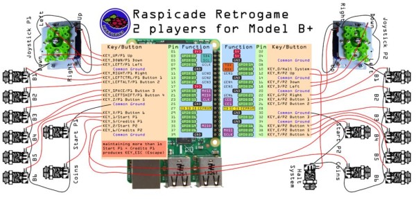
Raspberry Pi Atari Wiring Diagram
Raspberry Pi 3 Model B. The genesis of the Raspberry Pi came from a few college students concerned about the dwindling number and skills of students applying to study Computer Science.
 Raspberry Pi Atari Wiring Diagram 2001 Nissan Xterra Fuse Box Wirediagram Yenpancane Jeanjaures37 Fr
Then well configure a static IP for wireless interface wlan0 as it will be used from client devices as default gateway.

Raspberry pi atari wiring diagram. Build the circuit Connect the components as shown in the wiring diagram below. Join the global Raspberry Pi community. Raspberry Pi 4 B RP4 is the lasted model developed by the company which has all the required latest wired and wireless communications systems used in most of the smart projects.
The full breadboard diagram Connect the Moisture Sensor to the Raspberry Pi. GPIO 2 and GPIO 3 - the Raspberry Pis I2C1 pins - allow for two-wire communication with a variety of external sensors and devices. Newer computers and game consoles have replaced the old machines where most of us learned to program.
24x - GPIO pins. Make sure you have shut down your Raspberry Pi and unplugged its power cable. 5 minutes to read.
A single Raspberry Pi 4 comes to a Quad-Core. Theyre labeled in black in the diagram to the right. Similarly if the Raspberry Pi wants to turn the load OFF then de-energize the coil by sending a LOW signal.
Raspberry Pi is a small-sized computer used Linux operating system. Well start preparing Operating system. Each time a stealthy intruder breaks the laser beam the Raspberry Pi will sound the alarm via a buzzer or a speaker.
The only issue to deal with is converting the Pis GPIO from 33V up to about 5V for the NeoPixel to read. If you love Pinout please help me fund new features and improvements. Raspberry Pi Pinout Diagram Circuit Notes How to Navigate Your Raspeberry Pi 3 Model B If you build it they will program.
The following image shows the connections with respect to the project of How to Control a Relay using Raspberry Pi. Prior to the Pi 1 Model B 2014 boards comprised a shorter 26-pin header. Plugging in jumper leads while switched on may be tolerated by Raspberry Pi but in some cases it can cause a system crash or even damage to the hardware.
And to compare here is the Raspberry Pi pinout for more info here is a complete guide about Raspberry Pi 4 3B 3B pinout. The table is separated into 2 parts which are mirrored exactly as the Raspberry Pi pinout overview on the second image. All of the GPIO General Processing Input Output pins on the Raspberry Pi are digital so the Pi only supports digital.
Just as the layout and build technique of the control panel requires creative interpretation so too will you need to decide on your own wiring methodology. Now when an arcade button is pressed a GPIO pin will be connected to ground thereby changing the pin state from HIGH to LOW which will eventually be translated into a key press the software recognizes. In this resource you will use a laser pointer a few electronic components and a Raspberry Pi to make a laser tripwire.
Hardware interfaces for the Raspberry Pi 2 and Raspberry Pi 3 are exposed through the 40-pin header J8 on the board. This GPIO Pinout is an interactive reference to the Raspberry Pi GPIO pins and a guide to the Raspberry Pis GPIO interfaces. The Raspberry Pi GPIO pinout guide.
You will also need to solder up the 9-pin D connector. The Raspberry Pi has its own internal pull-ups. A 40-pin GPIO header is found on all current Raspberry Pi boards unpopulated on Pi Zero and Pi Zero W.
Raspberry Pi 2 3 Pin Mappings. 1x - I2C bus. The I2C pins include a fixed 18 kΩ pull-up resistor to 33v.
Connect the end of the ground chain to one of the Raspberry Pis GPIO ground pins. 2x - 5V power pins. We have some parts that can help.
The Raspberry Pi is a tiny and affordable computer that you can use to learn programming through fun practical projects. It is mini size computer used mostly to run larger and smart programs to achieve output quickly. Wiring diagram of Raspberry Pi With CNC Machine.
Please support me on Patreon. There are two ways you can do this level conversion either with a simple 1N4001 power diode or with a level converter chip like the 74AHCT125. Wiring NeoPixels to work with a Raspberry Pi is quite simple.
A powerful feature of the Raspberry Pi is the row of GPIO general-purpose inputoutput pins along the top edge of the board. Pinout also includes dozens of pinouts for Raspberry Pi add-on boards HATs and pHATs. Which model of Raspberry Pi you use is up to you but unless you have a specific use case in mind a Raspberry Pi Zero W is the perfect choice as its small and theres little horsepower required.
The table you see with gpio readall is quite complete it gives you a lot of useful information. 1x - Serial UARTs RPi3 only includes mini UART 2x - SPI bus. Please find in following picture wiring diagram in case of Raspberry PI Zero W.
The diagram Figure 1 shows the connector from the solder rear side. They are not suitable for use as general purpose IO where a pull-up might interfere.
 Raspberry Pi Arcade Game Emulator In An Atari Lynx Raspberry Pi Projects
Atari 2600 Pi Project Raspberry Pi Forums
 Sio2pi Atari 800 Raspberry Pi Blog Lmorchard Com


